
Coil insulators are recommended for all metal coils that will be installed in an electrified plating tank. The coil insulators are simply pipe couplings fabricated from a non-conducting material. The purpose of the coil insulators are to prevent a stray voltage from traveling to the immersion coil and give the coil an anodic or cathodic charge, either of which could result in corrosion or plate-out on the coil.

The purpose of the ground connection is to minimize the chance of a shock hazard for an operator or equipment. A ground connection on an electric immersion heater is required by the National Electric Code and is also a required part of the UL Listed construction.

Often enough to avoid buildup, although frequency varies upon application, solution, frequency of use, etc. Contact your chemical supplier for specific cleaning instructions.

When energized, the surface temperature of an electric immersion heater is much higher than the bulk liquid temperature. Since the tank walls are not the source of heat, they are typically the same temperature as the bulk liquid temperature. In addition, the heater sheath is much thinner than a typical metal tank wall. When you consider that many chemicals are more aggressive or react more quickly at elevated temperature (such as on the surface of an electric immersion heater), the heater sheath may be subject to chemical attack when the tank wall is not.

Almost all of our electric heaters are UL listed (cULus, which includes CSA approval for Canada) and CE compliant. Our temperature controllers are UL Listed, and many of them are also CE compliant. There are a few exceptions, so please refer to the product data sheet or the web page pertaining to a specific product to verify its approvals.


Yes. There is no price difference for making a heater with a short riser, but there may be a cost adder for a longer riser. Please contact our customer service department for more information.

Amp-hour meters are used to track the amount of amp-hours used in a plating tank. Using an amp-hour meter to track the consumption of amp-hours can help measure the amount of metal that is plated onto a batch of parts, calculate the depletion of plating metals in the plating chemistry, and calculate the amount of emissions emanating from the tank. In the United States, non-resettable amp-hour meters are required for measuring emissions in chrome plating process tanks.

No. For a recommended annual calibration of your amp-hour meter, we suggest you contact our customer service department who can quote the calibration charges, the lead time for the procedure, and facilitate the return of the meter to our factory for calibration.


The “UUU” message typically denotes a bad temperature sensor. If you have a replacement temperature sensor available, try replacing the sensor on the controller. If this does not correct the error message, please contact our service department for additional support. You may also want to visit our comprehensive page of downloadable .pdf files including manuals for controls.

Our industrial electric immersion heaters are designed to heat a variety of non-flammable aqueous (mostly water) process chemistries. Metal heaters are designed and built with a standard watt density of approximately 35W/sq. in. These heaters perform well when the process chemistry has a viscosity and heat capacity close to that of water. However, certain process chemistries (i.e. concentrated sodium hydroxide, glycols, oils) have a higher viscosity and/or lower heat capacities. Therefore, they are unable to absorb the heat and move it away from the surface of the heater quickly enough. For process chemistries like this, we recommend “derated” heaters - a heater with a watt density below 20W/sq. in. PTFE-covered heaters with a standard watt density of 10W/sq. in. area are already considered to be derated.

The heater sheath overtemperature “protector” fuse is a required safety device. It is designed to detect when the heater sheath exceeds a predetermined temperature, and trip. The protector must be wired such that when it trips all of the heaters operating in that tank are shut off.

Yes, we have changed our designations for protectors in our model numbers and assigned a part number for replacements. For example PII is now P2. Click here for a cross reference chart.

The LCBA5 liquid level control can be added to any temperature control box as a field upgrade.
Wiring Instructions (Note: The following procedure should only be performed by qualified personnel):
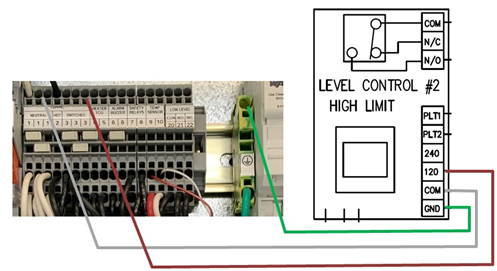
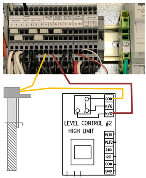
Test the wiring by making sure that when the LCBA5 level control detects no liquid the heater will not energize.

The LCBA5 liquid level control can be added to any temperature control box as a field upgrade.
Wiring Instructions (Note: The following procedure should only be performed by qualified personnel):
1. Turn off power to the control box and apply any lockout/tagout devices as required. Open the door.
2. Add three new wires to provide power to the circuit board, connected as follows:
a. Add a green wire from the GND terminal on the LBCA5 board to one of the green ground terminals inside the control box.
b. Add a wire from the COM terminal on the LCBA5 board to an open position on terminal block #1.
c. Add a wire from the 120V terminal on the LCBA5 board to an open position on terminal block #3

3. Modify the control wiring to integrate the level control output to the heater control circuit as follows: a. Disconnect the lead wire for the electric heater’s over temperature protector from terminal block #5. b. Extend this wire to the LCBA5 box and connect it to the COM terminal for the output switch. c. Add a new wire from the N/O position on the LCBA5 circuit board to terminal block #5 in the control
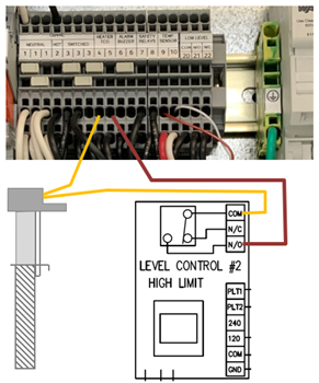
Test the wiring by making sure that when the LCBA5 level control detects no liquid the heater will not energize.

The ESP liquid level control can be added to any temperature control box as a field upgrade. Please note that this method of wiring does not provide a low-level indicator light for the operator.
Wiring Instructions (Note: The following procedure should only be performed by qualified personnel):
1. Turn off power to the control box and apply any lockout/tagout devices as required. Open the door.
2. Disconnect the lead wire for the electric heater’s over temperature protector from TB5.

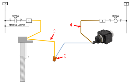
3. Using a wire nut, make a connection between the disconnected wire and one of the ESP lead wires (polarity and wire color does not matter here.)
4. Attach the remaining ESP lead wire to TB5.
5. Calibrate the ESP per the instructions provided in the product manual.
Test the wiring by making sure that when the ESP level control detects no liquid the heater will not energize.

The T-DRA15-1 temperature controller is rated to control a 120V electric heater which draws 12-amps or fewer.
Note: The wiring instructions provided below illustrate using wire nuts. Be sure that the wire nuts or terminals used for the wiring are rated for the supply voltage, amp draw of the heater, and the number of wires which will be connected by them.
Note: The following procedure should only be performed by qualified personnel
Wiring Instructions for an “A” series electric heater (ex: SA, TA, LSA, LTA series) The “A” series electric heaters come with a 3-conductor cord:

Wiring Instructions for a standard electric heater with a P1 protector.The standard electric heaters come with a flexible conduit and 5-wires; two black, two yellow and one green:


RTD Temperature sensors come in 2-wire, 3-wire and 4-wire types. The third and fourth wires are connected in parallel to the other wires, which allows the measuring device to detect and compensate for the resistance of the lead wires.
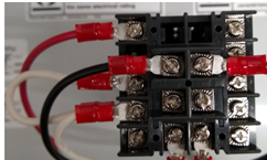
How to connect a 2-wire RTD sensor to the input connections for a 3-wire RTD sensor:


Regulation mode describes how the power supply will operate in regards to the output load and desired voltage and current settings. The individual plating process will determine which mode to use.
There are three regulation modes available in all power supplies:
Voltage : The output voltage is regulated to the setpoint while the output current will vary according to the load. For example, barrel plating processes often use voltage regulation.
Current : The output current is regulated to the setpoint while the output voltage will vary according to the load. For example, rack plating processes often use current regulation.
Crossover : In this mode both current and voltage outputs are set at a desired level (i.e. 6 VDC, 95 Amps). The output will either be current regulated or voltage regulated depending on output load. The crossover point is defined as the point where the power supply switches from one regulation mode to the other. See illustration below.


Three single-phase heaters of the same wattage and voltage can be wired in DELTA to create a balanced three-phase load.
Wiring Instructions:
Arrange the heater wires to the load-side of the switching contactor (positions T1, T2, and T3) as follows :
a. The two heater wires from heater 1 go to positions T1 and T3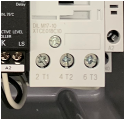

The result is a balanced three-phase load for the power circuit. There will be two heater wires per position on the switching contactor, which is the allowable limit for these devices.
If there is a need to connect more than one DELTA group to a single temperature controller, then a junction box or a branch fuse box is required.

The DTX2400 power supply has an output which can be connected to an external light or buzzer to provide a remote alarm.
Wiring Instructions:


The DQ15D-series temperature controller has a second output relay and set point which can be used to operate a solenoid valve for a cooling load. This output is not usually pre-wired at the factory. Here are the steps to wire a 120V solenoid valve to this output.
Wiring Instructions:


The DQ15D temperature controller has two set points; SP1 for heating and SP2 for cooling. The SP2 output relay is not pre-wired to any terminals. Here are the steps to wire a 120V solenoid valve to this output:
Wiring Instructions:


The calculation for the amp draw of electric heaters is slightly different for single-phase and three-phase heaters.
Amp draw calculation for single phase heaters:
Amps = Heater Watts (W) ÷ Voltage (V)
Example: 6000W ÷ 208V = 28.8 amps
Amp draw calculation for three phase heaters:
Amps = Heater Watts (W) ÷ Voltage (V) ÷ 1.73
Example: 6000W ÷ 208V ÷ 1.73 = 16.7 amps
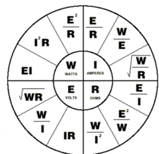
This table shows different calculations for Watts, Amperes, Volts or Ohms based upon Ohm’s Law.

When considering a pulsed DC power supply, it is important to understand the peak current, average current and duty cycle. Understanding these terms and how they relate to each other will help with power supply selection and setup. The following explains each and their relationship to each other.
Below is an example of a basic pulsed DC output
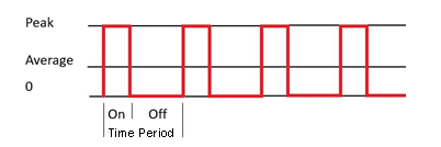
Peak Current: The output current the power supply will regulate during the pulse on time
Duty Cycle: = On Time ÷(Time Period)
Average Current: = Peak Current X Duty Cycle
The DC equivalent (effective current) is used for calculating amp minutes and total power.
Frequency: = 1 ÷ (Time Period)
Example:

Average Current: = 1ms ÷ (1ms + 2ms) = .33 Duty Cycle
= 1 Amp X .33s = .333 Amps Average
Frequency: = 1 ÷ 3ms or 1 ÷ .003s = 333Hz

The calculation for the resistance of an electric heater is slightly different for single-phase and three-phase heaters. Please note that the exact resistance of an electric heater may vary by a few percent due to manufacturing tolerances. Your heater may measure a little higher or lower than the calculation below (within 10%).
Resistance calculation for single phase heaters:
Ohms = (Voltage (V))2 ÷ Heater Watts (W)
Example: (208V)2 ÷ 6000V = 7.2 Ohms
Resistance calculation for three phase heaters:
Ohms = [(Voltage (V))2 ÷ Heater Watts (W) ] x2
Example: [(208V)2 ÷ 6000V] x2 = 14.4 Ohms
This table shows different calculations for Watts, Amperes, Volts or Ohms based upon Ohm’s Law.

